[コンテンツ]
開発環境の動作確認のために評価基板を作成します。 評価する開発環境は、統合開発環境(MPLAB X IDE)、コンパイラ(MPLAB XC)、サーキットデバッガ(PICkit 3)です。
●PIC16F1827評価基板
まずは、定番のLEDがチカチカする回路を作りました。電源は、DC 3.3V及び5Vで動作確認済みです。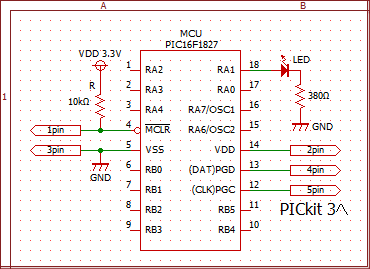
※さらに、安定動作させるため VDD(14pin)→パスコン(0.1uF)→GNDと追加接続するのが良いでしょう。
ブレッドボードに回路を実装して、当サイトの<MPLAB X IDEの使い方>のプロジェクト作成とコードコンフィグレーションで記載したサンプルプロジェクトをベースに、LED点滅のためのRA1ポート(Digital-out設定した)を設定したコードコンフィグレーションと main.cを以下に記載します。 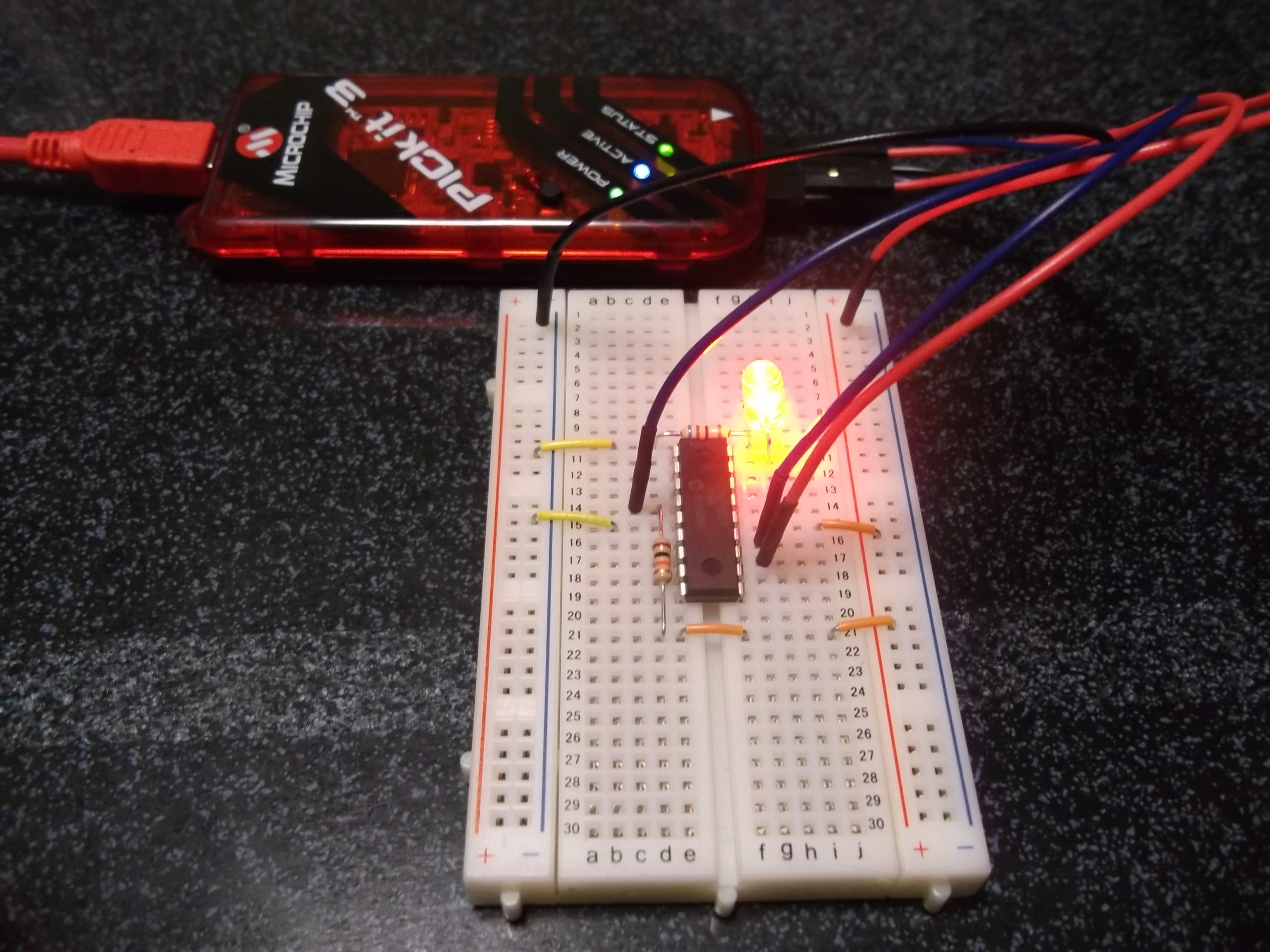 以下コンフィグレーションは、動作クロック16MHz(内部クロック16MHz)で動作します。
動作クロック32MHz(内部クロック8MHz×PLL4倍)にしたい場合は、config PLLEN=ON、OSCCON = 0x70; に変更します。
#include "mcc.h"

// Configuration bits: selected in the GUI
#pragma config FOSC = INTOSC    // Oscillator Selection->INTOSC oscillator: I/O function on CLKIN pin
#pragma config WDTE = OFF    // Watchdog Timer Enable->WDT disabled
#pragma config PWRTE = OFF    // Power-up Timer Enable->PWRT disabled
#pragma config MCLRE = ON    // MCLR Pin Function Select->MCLR/VPP pin function is MCLR
#pragma config CP = OFF    // Flash Program Memory Code Protection->Program memory code protection is disabled
#pragma config CPD = OFF    // Data Memory Code Protection->Data memory code protection is disabled
#pragma config BOREN = ON    // Brown-out Reset Enable->Brown-out Reset enabled
#pragma config CLKOUTEN = OFF    // Clock Out Enable->CLKOUT function is disabled. I/O or oscillator function on the CLKOUT pin
#pragma config IESO = OFF    // Internal/External Switchover->Internal/External Switchover mode is disabled
#pragma config FCMEN = ON    // Fail-Safe Clock Monitor Enable->Fail-Safe Clock Monitor is enabled
#pragma config WRT = OFF    // Flash Memory Self-Write Protection->Write protection off
#pragma config PLLEN = OFF    // PLL Enable->4x PLL disabled
#pragma config STVREN = ON    // Stack Overflow/Underflow Reset Enable->Stack Overflow or Underflow will cause a Reset
#pragma config BORV = LO    // Brown-out Reset Voltage Selection->Brown-out Reset Voltage (Vbor), low trip point selected.
#pragma config LVP = OFF    // Low-Voltage Programming Enable->High-voltage on MCLR/VPP must be used for programming

void SYSTEM_Initializer(void)
{
    OSCILLATOR_InitializerDefault();
    PIN_MANAGER_Initializer();
}


void OSCILLATOR_InitializerDefault(void)
{
    // SPLLEN disabled; SCS FOSC; IRCF 16MHz_HF;
    OSCCON = 0x78;
    // OSTS intosc; HFIOFR disabled; HFIOFS not0.5percent_acc; PLLR disabled; T1OSCR disabled; MFIOFR disabled; HFIOFL not2percent_acc; LFIOFR disabled;
    OSCSTAT = 0x00;
    // TUN 0x0;
    OSCTUNE = 0x00;
}
#include <xc.h>
#include "pin_manager.h"

/****************************************************************************
 *
 * Prototype:		void PIN_MANAGER_initializer(void)
 * Input:	    	none
 * Output:	    	none
 * Description:    	GPIO and peripheral I/O initialization
 * Usage:          	PIN_MANAGER_initializer();
 *
 ***************************************************************************/

void PIN_MANAGER_Initializer(void)
{
    LATA = 0x00;
    TRISA = 0xFD;
    ANSELA = 0x1D;
    WPUA = 0x00;

    LATB = 0x00;
    TRISB = 0xFF;
    ANSELB = 0xFE;
    WPUB = 0x00;

    IOCBP = 0x00;

    IOCBN = 0x00;

    IOCBF = 0x00;

    APFCON0 = 0x00;

    APFCON1 = 0x00;
}
#include <xc.h>
#include "mcc.h"

void main(void) {
    int i;

    SYSTEM_Initializer();
    OSCILLATOR_InitializerDefault();
    while(1)
    {
        IO_RA1_SetHigh();
        for(i=0; i < 0xF000; i++);
        IO_RA1_SetLow();
        for(i=0; i < 0xF000; i++);
    }
    return;
}
※ mcc.c(.h)、pin_manager.c(.h)は、MPLAB Code Configratorで生成されたファイルです。
< PICマイコン >